Resistance
- It is the opposition of the flow of current. It is measured in Ohms (Ω).
- When applying a fixed potential difference across different components in a circuit, different values of current flow because the different components resist the flow of electrons by different amounts.
An experiment to determine resistance
- To determine the resistance of a load, a simple circuit using an ammeter and a voltmeter

- Adjust the variable resistor to allow the smallest possible current to flow in the circuit and record corresponding ammeter and voltmeter reading.
- Adjust the variable resistor to allow a larger current to flow in the circuit and note the values of I and V.
- Repeat the above for five sets of I and V readings
-
Plot a graph showing V against I, and determine the gradient of the graph. – The gradient of the graph gives the resistance of the load, R.

- The graph is a straight line passing through the origin thus current is directly proportional to the voltage across the resistor
OHM’S LAW
– The Ohm’s law states that the current through a metallic conductor is proportional to the potential difference across the conductor provided temperature remains constant. This means that current increases in the same ratio as when voltage increases

 𝑉 = 𝐼𝑅
Examples 1
A p.d measured across a light bulb is 12V. The current measured is 5A.
Calculate resistance
Example 2
A potential difference of 240V applied across the heating coil of an electric kettle drives a current of 8A through the coil. Calculate
- The resistance of the coil
- The new current flowing through the coil if the p.d. applied is changed to 220V
Limitations of the Ohm’s law
- Temperature – if temperature increases, the resistance also increases and if it decreases resistance also decreases. This will cause variations in the answers when using Ohm’s law
-
Ohm’s law is not obeyed when
- Temperature of conductor changes e.g. bulbs and heater elements
- The conductor is cooled
- The conductor does not have a uniform cross sectional area
Factors that affect resistance
- Length of the conductor – resistance increases with an increase in length of the material. The longer the wire, the greater the resistance it has
- Thickness of the conductor (cross sectional area) – resistance increases with an increase in cross sectional area. The larger the cross sectional area of a wire, the smaller the resistance it has.
- Temperature – higher temperature offers more resistance
SIMPLE ELECTRIC CIRCUITS
– In the study of current electricity, it is vital to draw simple and clear diagrams. The following diagrams gives a list of special symbols that are used to represent common devices that are usually employed in electric circuits

Representing some circuit diagrams using electric symbols

Resistors
- Conductors intended to have resistance are called resistors and are made either from wires of special alloys or from carbon.

- The primary purpose of resistors is to control the size of the current flowing in a circuit. Resistors in series

- The same current I flow through each and the total voltage V across all three is the sum of the separate voltages across them.
V = V1 + V2 + V3
But 𝑉1 = 𝐼𝑅1, 𝑉2 = 𝐼𝑅2 and𝑉3 = 𝐼𝑅3. Also, if R is the combined resistance, 𝑉1 = 𝐼𝑅1 and so:
𝐼𝑅 = 𝐼𝑅1 + 𝐼𝑅2 + 𝐼𝑅3
Dividing both sides by I,
𝐑𝐭𝐨𝐭𝐚𝐥
= 𝐑𝟏 + 𝐑𝟐 + 𝐑𝟑
Parallel arrangement of resistors
- The p.d. across the two resistors in parallel is the same. In addition, the current (I) flowing into the common point splits into I1, I2 and I3 and rejoins into I.

- The voltage V between the ends of each is the same and total current I equals the sum of the currents in the separate branches, i.e.
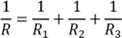
For the simpler case of two resistors in parallel

- For more than two resistors in parallel, the reciprocal of the total resistance of resistors connected in parallel is equal to the sum of reciprocal of each individual resistors
