Generator Notes
Generator effect
- When a conducting wire is moved through a magnetic field, a voltage is generated along the conductor. This causes a change in the magnetic field, called a magnetic flux. This called generator effect. The voltage induced is the e.m.f
- An e.m.f can be induced when a magnet is moved through a current carrying coil. The rotation of the coil in a magnetic field induces an e.m.f in the coil.
An experiment which show that a change in magnetic field can induce electromotive force (e.m.f) in a conductor.

When the magnet approaches the coil, north-pole first, the induced current should flow in a direction that makes the coil behave like a magnet with its top a north pole.
The downward motion of the magnet will then be opposed since like poles repel.
- When the magnet is withdrawn, the top of the coil should become a south pole and attract the north pole of the magnet, so hindering its removal. The induced current is thus in the opposite direction to that when the magnet approaches
-
When there is a change in the magnetic lines of force passing through the coil, an
e.m.f is induced in the conductor.
Factors which affect the magnitude of induced e.m.f.
- Strength of a magnet -a stronger magnet induces a stronger e.m.f
Relative motion – moving or rotating the conductor (coil) faster induces a stronger e.m.f
- Number of turns – the more the turns are in the coil, the stronger the induced e.m.f
- Area of coil the larger the area that the magnetic field acts over the stronger the induced e.m.f
Simple d.c. generator
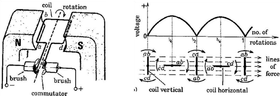
- It has split ring commutator
- As the coil rotates in the magnetic field of a permanent magnet, it cuts across magnetic lines of force at right angles causing a change in the magnetic field (flux). This change induces an e.m.f through the coil, so current is through the coil.
- The brushes are arranged so that as the coil goes through the vertical, changeover of contact occurs from one half of the split ring of commutator to the other. But it is when the coil goes through the vertical position that the voltage induced in the coil reverses, so one brush is always positive and the other negative
- From the graph shown; although varying in value, it never changes direction and would produce a direct current(d.c.) in an external circuit
- The e.m.f on the graph always has positive value. When the coil is vertical, no magnetic field lines are being cut by the coil, hence no current.
- When the coil is horizontal, the coil is cutting the field lines, hence maximum current in the coil.
Simple a.c. generator

- As the coil rotates the magnetic field through the coil changes and therefore induces an e.m.f. between the ends of the coil. The induced current does not flow unless the ends of the coil are connected to an external circuit with an electrical load. The slip rings allow the transfer of alternating e.m.f. induced in the rotating coil to the external coil.
- Each ring is connected to one end of the coil wire and electrically connected by a carbon brush to the rest of the circuit. The brushes on the coil touch the slip rings while the coil rotates for a full, continuous cycle thus causing the current in the external circuit to change direction every time the coil makes half turns. An a.c current is generated
- The current in the external circuit changes direction every half revolution.
- As the coil moves through the vertical position with ab uppermost, ab and cd are moving along lines (bc and da do so always) and no cutting occurs. The induced voltage is zero